To simulate, or not to simulate: that is the question. Tis nobler (or at least more efficient) to spend the time to create simulation models and test the design prior to deployment, or to spend the time testing the design during deployment?
While I can’t speak for Shakespeare, I can say in my nearly 40-year career “tis” always been more efficient to perfect the design prior to deployment. I have successfully applied simulation to applications including many different types of industrial controls (IC) systems, electronic printed circuit board (PCB) design, and field programmable gate array (FPGA) design.
Five paybacks from simulation
Simulation pays for itself many times over due to:
- The insight simulation models provide, which can’t be measured or observed in the actual plant or equipment
- The ability to determine the merits of alternate approaches and choose the option with the lowest overall cost or the best overall performance
- The ability to test emergency and unusual conditions, which are impossible or dangerous to do with the real equipment
- The high level of confidence in the design, which provides the corresponding confidence that any issues encountered during commissioning must be in the plant or equipment.
- The ability to perfect the control in parallel to the construction of the plant or equipment (and avoid the inevitable pressure from the anxious project manager looking for those who reside at the end of the critical path to make up for delays earlier in the project).
This return on investment (ROI) becomes even greater with modern development and simulation environments, which include object-oriented industrial programming (OOIP) techniques to accelerate development, and advanced debugging features that accelerate the time-to-insight.
Strong simulation elements
The characteristics of a good IC simulation environment look very similar to a good IC development environment:
- Versatile and powerful programming languages
- Full featured language editors
- Full suite of debugging tools including code and data breakpoints; single-stepping, step-in, step-out, etc.; live mode (to show instantaneous variable values, not just end of cycle values); write and force variables and move the execution point; and virtual digital oscilloscope which samples at the controller cycle time
- Built-in human-machine interface (HMI) for creating test control panels
- A complete controller runtime, which runs as a service on the development computer Support for OOIP.
Creating the simulation code in such an environment is as easy as creating the original code, and it can run as a software-based programmable logic controller (PLC), which is the same full-featured runtime that industrial controller OEMs deploy on their hardware. This runtime is installed as a Microsoft Windows service independent of the development environment. The control code created and compiled in the integrated development environment (IDE) and deployed to this runtime the same way it is to a PLC or distributed control system (DCS).
Example reactor tank
Consider the example of a simple reactor tank with a variable speed outlet pump to maintain fluid at a preset level (regardless of the inlet flow rate). The concepts can be extrapolated to larger systems and in other industries.
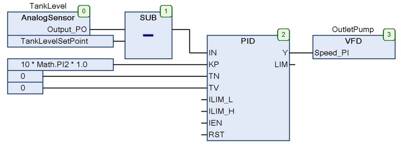
The first step is to design the control system. Using OOIP techniques, instantiate four objects from the plant object library: an analog input for the tank level, a subtraction for the setpoint, a proportional-integral-derivative (PID) loop for the control, and a variable frequency drive (VFD) for the pump motor, as shown in Figure 1.
With OOIP techniques, all the remaining functionality is encapsulated within these objects, such as the scaling and alarming for the analog input, and fieldbus communications for the VFD.
In this example, the plant has a tank that takes 10 seconds to fill at 100% flow rate, which equates to a pole at 0.0 Hz with a gain of 1/(10*2πf). For a loop bandwidth of 1.0 Hz, apply a proportional gain of 10*2π as shown in Figure 1. This provides a phase margin of nearly 90 degrees and a high level of stability.
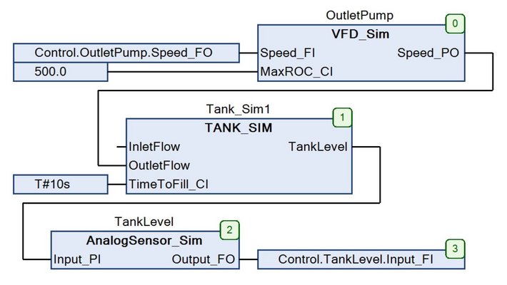
The next step is to design the plant simulator. The form of the simulator program mirrors the control, with a VFD input, a tank model, and an analog output object, which are all from the simulation object library shown in Figure 2.
Again, each object encapsulates all the functionality necessary to carry out the function of the object. For instance, the tank integrates the difference between the input flow and the output flow and limits the integration to tank full or tank empty as shown in Figure 3. The tank model is an example of how simple it is to build simulation objects and by extension the simplicity of adding simulation to a workflow.
In the example, configuration inputs and the I/O mapping in the control and simulation programs are hard-coded. In a larger OOIP design this would be configured from a central SQL server or CSV file so the design could be reused.
Notice the simulator inputs are mapped to the control outputs and the simulator outputs are mapped to the control inputs. The physical I/O is mapped in the same way using the same full-path names (that is, Control.OutletPump.Speed_FO).
Virtual testbench
The next step is to create the testbench. Just like the physical bench from which the name was coined, the virtual testbench provides all the inputs the system needs including: upstream process inputs, operator inputs, and configuration inputs. These process inputs could be generated from an HMI screen for a manual test or from a program for an automated test.
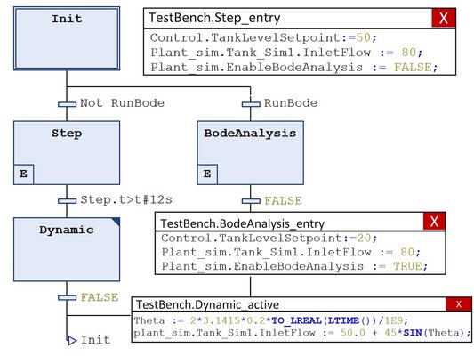
Likewise, the HMI inputs could be programmatically generated for an automated test or could be generated from the actual HMI screens (in which case the simulation system could double as a plant operator training tool). This example generates the stimulus programmatically with a sequential function chart (SFC) program, which first performs a step response, followed by a steady state as shown in Figure 4. This SFC also provides the option to perform a Bode loop analysis to find the poles and zeros of the control loop.
The testbench also could include programmatic measurement and analysis to create an automated test bench. An automated test bench allows the system to be verified under multiple scenarios and allows the system to test itself after any future modifications. This is particularly true for future modifications made by engineers who are not as familiar with the original system design.
The next step is to place these objects into tasks as shown in Figure 5. The control is assigned to its normal task, in this case with a 20 milliseconds (ms) cycle time. Since the simulator and testbench need to mimic the plant and plant operator, which both run in real-time, the simulator task is assigned a cycle time that is much faster than the control task. To avoid any possible synchronization issues that could mask potential control problems, the simulator task also is assigned a non-integer submultiple rate of the control task (3 ms).
The last step is to download and run the program on the built-in software-based PLC.
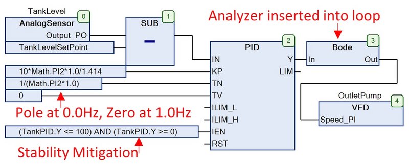
Just as in a physical testbench, various measurement equipment is used to verify the system’s proper operation. One such virtual instrument is a Bode loop analyzer, which measures the poles and zeros of the control loop as well as the gain and phase margin. This instrument is inserted into the loop as shown in Figure 8.
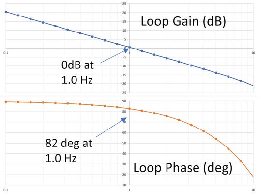
This can be used to test various control scenarios during simulation as well as to verify and tweak the control loops in the actual factory or plant. The results of this analysis show a crossover frequency of 1.0 Hz and a phase margin of 82 degrees as shown in Figure 6.
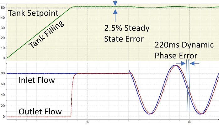
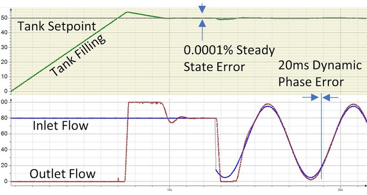
Another useful test instrument is a virtual oscilloscope, which shows the step and dynamic responses of the reactor system as shown in Figure 7. It should be noted this oscilloscope runs on the target hardware so it is guaranteed to capture a sample on every cycle, even at microsecond cycle times.
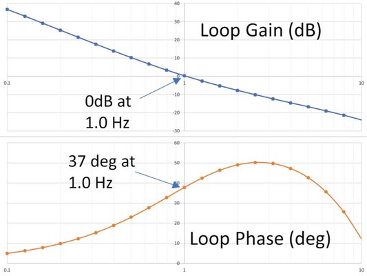
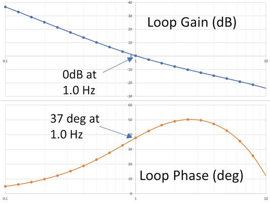
If this first order control loop performance did not meet the system requirements, it’s possible to enhance the PID with a pole at 0.0 Hz and a zero at 1.0 Hz to improve the accuracy at the cost of stability (which requires mitigation) as shown in Figure 8. This second order system now provides much higher loop gain and a phase margin of 37 degrees as shown in Figure 9; and delivers a much better steady-state dynamic response shown in Figure 10.
Process, batch, discrete
In addition to continuous process, these techniques can be applied to batch and discrete processes, as well as mobile, embedded, or any other industrial automation. Simulation models have been created for conveyors, bottlers, dry ingredient augers, systems of pipes and valves, and numerous other applications. Just about any industrial process can be sufficiently modeled to allow for simulation.
This simple example demonstrated the insight that can be gained with simulation, the tradeoffs that can be measured and chosen with simulation, the confidence gained by simulation, and the valuable progress simulation can accomplish before the actual hardware becomes available.
These techniques can be applied to nearly any industrial application and scaled to systems of any arbitrary size or complexity.
As Shakespeare would say: “To do a great right do a little wrong.” He would have approved of using simulation to further that goal.
Mehr Informationen finden Sie im begleitenden Video.
Der Artikel wurde in "Control Engineering", Ausgabe April 2019, veröffentlicht.
Gary L. Pratt, P.E., ist President von ControlSphere LLC. Verantwortlicher Redakteur: Mark T. Hoske, Control Engineering, CFE Media, mhoske @cfemedia.com.


